21 Density and real liquid interfaces
A liquid state needs more than a smoke concentration. Its interface locates a liquid domain, its density supplies inertial mass, and its volume ledger records transport and sources. Changing the grayscale opacity coefficient does not produce a liquid. This chapter specifies an incompressible, immiscible Newtonian research model. Compressible flow, phase change and dissolved materials are separate extensions.
Constant material and multiple phases
A single liquid with negligible air dynamics can use constant positive in active liquid cells and a pressure boundary at the interface. A two-phase model solves momentum in both phases with densities . These choices have different pressure masks and inertia. The choice must remain visible in state and output metadata.
For variable density, the pressure coefficient uses inverse density at the pressure connection. Across a one-dimensional layered connection of lengths , integrating gives effective . This is the harmonic transmissibility of the inverse-density coefficient, not a universal average independent of geometry. Volume-fraction mixing is another declared approximation. Use the same coefficient in assembly and velocity correction.
positive_transmissibility proves positivity from
positive area, density and distance.
weighted_pressure_energy proves the corresponding
weighted-square sum is nonnegative; Chapter 16’s existing matrix
identity explains its operator interpretation. Neither identifies the
physically correct density interpolation at an unresolved interface.
Hydrostatic oracle
Take upward y, gravity , and free surface at . For piecewise layers,
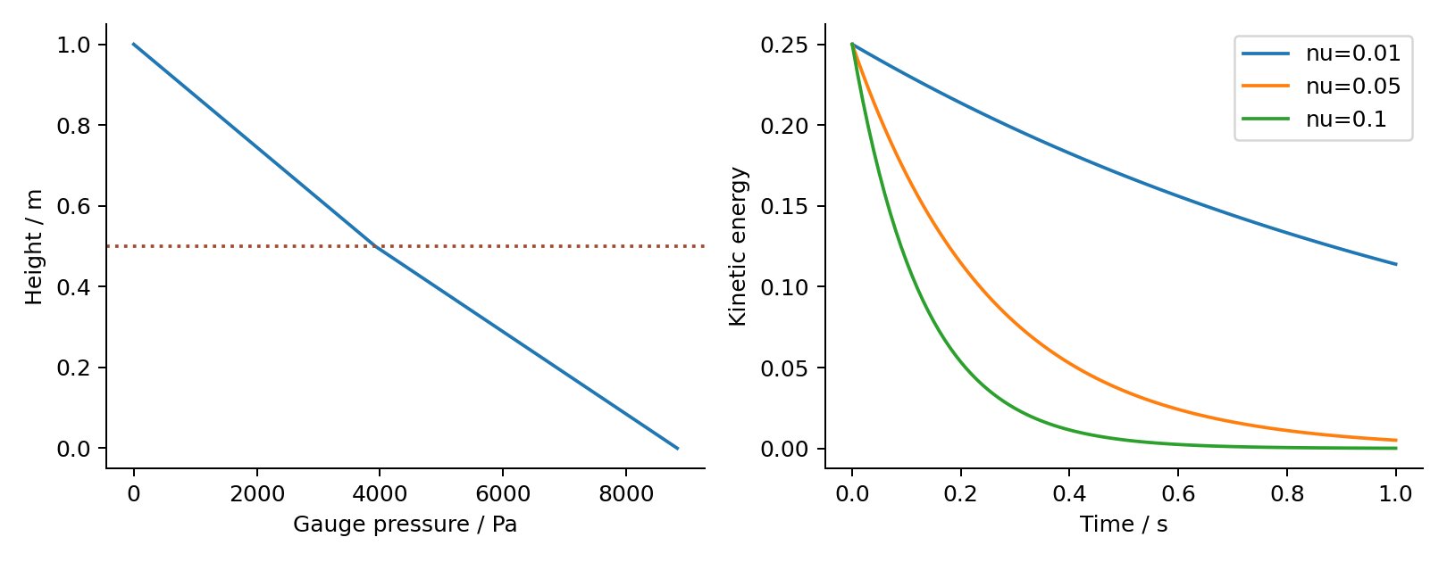
A discrete face increment cancels a gravity step when the same face density is used. The reference tank has a lower layer of density 1000 and an upper layer of 800 kg/m³, each 0.5 m deep. With g=9.81 m/s² its bottom gauge pressure is 8829 Pa. These are illustrative parameters, not a measured material calibration or a stable stratified-flow simulation.
The educational tank displays the stored layer density and pressure
samples. Increasing density changes pressure and inertia; it does not
change equilibrium cap geometry at zero gravity. That distinction
prepares the later capillary lab. hydrostatic_increment
checks the exact cancellation identity for a prescribed face balance; it
does not prove long-time rest after transport, interface reconstruction
or rounding.
Conservative represented volume
Let , with . Update using one signed shared face flux. In this amount ledger B is outward-positive (positive at the face tail, negative at its head), the negative of Chapter 16’s pressure incidence. The conservation result is unchanged by this global sign choice. Balanced incidence columns imply
volume_source_balance proves this identity in exact
arithmetic for arbitrary finite cell volumes. The proof operates on
represented amounts; it does not establish fraction bounds or determine
geometrically correct fluxes. Post-update clamping can violate the
identity. The original three-cell volume fixture checks unequal volumes
and a nonzero source using rational arithmetic before exporting floating
values.
Chapter 9’s axis-aligned PLIC example remains a local geometric oracle. Full three-dimensional bounded conservative transport needs one coherent multidimensional outflow scheme, consistent reconstruction normals and source treatment. A level-set branch instead needs measured volume drift and an explicit correction policy. Neither is selected merely because it yields a smoother surface image.
State and failure contract
Proposed LiquidState retains interface representation,
positive material parameters, volume/source totals, pressure-unknown
mask and velocity-validity mask. Those masks are distinct. Air velocity
extension supports transport without making extended air cells physical
liquid. Rebuild topology and preconditioners when classification or
density policy changes. A failed interface reconstruction must not
publish pressure and geometry from different versions.
Acceptance progresses through hydrostatics, translating sphere, oblique interface transport, merging volumes and thin films. Report both represented volume error and spatial interface error; equal volume does not establish equal shape. Two-phase density-ratio tests additionally require momentum-transfer and pressure-jump checks. The original VOF and level-set works remain primary method references [S8–S10], while the present fixtures are independently constructed.
Holding one material quantity fixed
Increasing density at fixed dynamic viscosity lowers ν=μ/ρ; increasing density at fixed ν raises μ. A single-phase prescribed gravity acceleration stays the same, while hydrostatic pressure and inertia change. A fluid material API must record which viscosity quantity is supplied. The inspected original SPlisHSPlasH Weiler2018 code multiplies its configured viscosity by rest density to obtain μ R14. Copying a GUI value between solvers without converting its definition is therefore unsafe as a material comparison.
Represented particle mass, reference density, estimated density and particle count also differ. For uniform reference sampling m=ρ₀V₀. Removing particles removes represented mass unless explicitly accounted as boundary/source flux. A planar 2D formulation must declare an out-of-plane thickness or use per-unit-depth quantities; a 3D coefficient cannot be transferred by a screenshot comparison.
For pressure-driven planar Poiseuille flow with G=−dp/dx>0, u(y)=Gy(H-y)/(2μ) and flow per width Q′=GH³/(12μ). The equivalent acceleration is G/ρ, with units m/s². The bounded native forced-column operation now supplies this force/density/viscosity cross-check using a uniform body force, without solving a pressure gradient. At fixed G the steady speed depends on μ while density changes viscous relaxation; at fixed acceleration the effective force density changes with ρ. Its recorded startup lab compares the actual explicit algorithm against both the continuum steady profile and the distinct endpoint-basis equilibrium, plus a closed-form exact-real discrete transient. This fixed-slab operation does not qualify arbitrary channel meshes or variable-density liquid dynamics.